
|
|
| Brand Name: | Kingrail |
| Model Number: | 13 |
| MOQ: | 1 pc |
| Price: | Negotiable |
| Packaging Details: | standard export package, or as per customer request |
| Payment Terms: | L/C, D/A, D/P, T/T, Western Union, MoneyGram |
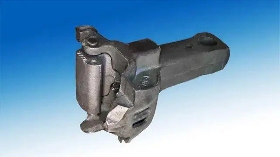
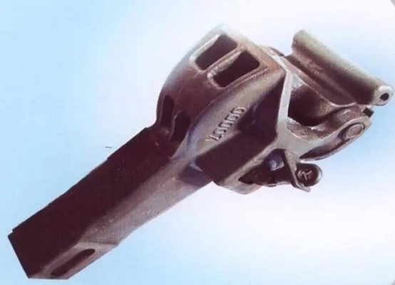
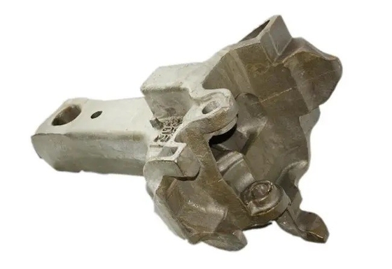
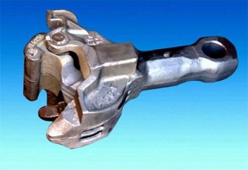
Kingrail Flexible Train Car Coupler For Railroad ISO Certificate ODM
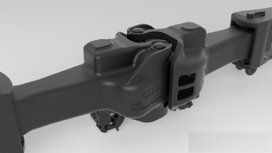
The coupler buffer device is a vehicle component used to connect the vehicle with the vehicle, the locomotive or the motor vehicle, transmit the traction force, the braking force and relieve the longitudinal impact force. It is composed of a coupler, a buffer, a hook tail frame, a slave plate, etc., and is installed in the traction beam at the end of the underbody frame. In order to ensure the safety and reliability of the vehicle connection and the interchangeability of the installation of the coupler buffer device, the relevant regulations of the railway locomotive and rolling stock stipulate that: after the coupler buffer is loaded, the horizontal center line of the coupler tongue is separated from the rail surface in the empty state. The passenger car is 880mm (+10mm, -5mm error is allowed), and the truck is 880mm (±10mm). The maximum height difference between the horizontal centerlines of the couplers of two adjacent vehicles shall not be greater than 75mm
The coupler is a vehicle component that is used to realize the connection between the locomotive and the vehicle or the vehicle and the vehicle, transmit the traction force and the impact force, and keep a certain distance between the vehicles. The coupler is divided into two types: upper-action type and lower-action type according to the opening method. The upper-action type is opened by the lifting mechanism on the upper part of the coupler head (generally used by trucks); the lower-action type (used in passenger cars) is opened by the action of the push lever at the lower part of the hook head. The coupler is divided into screw coupler, close automatic coupler, automatic coupler and rotary coupler according to its structure type. The screw coupler was used the earliest, but it has been eliminated due to many shortcomings. The close-contact automatic coupler is mostly used for high-speed railway vehicles. Except for the use of rotary couplers on heavy-duty unit trains on the Daqin Railway, China now uses automatic couplers. The so-called automatic coupler is a coupler that can automatically complete the action of decoupling or hooking when the lift rod of a coupler is first lifted, and then the vehicle is pulled away by a locomotive or collided with the coupler of another vehicle. In 1956, the Chinese Railway Department determined the No. 1 and No. 2 couplers as standard couplers. However, with the increase of train speed and tonnage, the No. 15 coupler and No. 13 coupler were designed and manufactured in 1957 and 1965. Passenger cars use the No. 15 coupler, and trucks gradually use the No. 13 coupler instead of the No. 2 coupler.
Component of Railway Coupler coupling for locomotive Rail Wagon Train Parts Railway Flexible Hinge Joint Coupler Coupling System
The coupler is composed of three parts: the hook head, the hook body and the hook tail. The thick part of the front end of the coupler is called the hook head. The rear of the coupler is called the hook tail, and there is a vertical flat lock hole on the hook tail to connect with the hook tail frame. In order to achieve hooking or unhooking, connecting or separating the vehicle, the coupler has the following three positions, that is, the three-state of the coupler: the locked position—the position where the hook of the coupler is blocked by the coupler locking iron and cannot be turned outward. The coupler is in this position when two vehicles are linked together. Unlocking position - that is, the position where the hook lock iron is lifted and the hook tongue can be turned outward as long as it is pulled. When removing the hook, as long as one of the couplers is in the unlocked position, the two linked cars can be separated. Fully open position—that is, the position where the knuckle has been fully turned outward. When two vehicles need to be linked together, as long as one of the couplers is in the fully open position, it can be linked after colliding with the other coupler. The structure of the rotary coupler is different from that of the ordinary coupler, the hook tail has a lock hole, and the hook tail pin is connected with the rotating sleeve of the hook tail frame. The end face of the hook tail is a spherical surface, which is pressed against the front and follower plate with a concave spherical surface. When the hook head is acted by torsional moment, the hook body rotates together with the tail pin and the rotating sleeve. The swivel coupler is only installed on vehicles specially designed for the Daqin railway coal transport unit combined train. One end of this kind of vehicle is equipped with a rotating coupler, and the other end is equipped with a fixed coupler. The two couplers connected in each group on the whole train are matched with each other. When the vehicle loaded with coal enters the dumper position in the coal unloading area, the dumper drives the vehicle to turn over 180 degrees to dump the coal. The rotating coupler can make the vehicle work continuously without removing the hook when the vehicle is turned over and unloading, which shortens the unloading operation time. Close-contact couplers are generally used on vehicles on high-speed railways and subways. It is small in size, light in weight, and the relative movement in all directions after the two couplers are connected is very small, which can realize a real "close connection"; at the same time, it is extremely beneficial to improve the reliability of automatic docking of brake hoses and electrical connectors.
buffer
The buffer is used to relieve the longitudinal shock and vibration caused by the change of the traction force of the locomotive during the operation of the train or the collision of the vehicles during starting, braking and shunting operations. The shock absorber has the function of dissipating shock and vibration between vehicles, thereby reducing the damage to the body structure and loaded goods. The working principle of the shock absorber is to moderate the impact force by compressing the elastic element, and at the same time use friction and damping to absorb the impact energy during the deformation process of the elastic element.
Cushioning Principle Of Railway Coupler coupling for locomotive Rail Wagon Train Parts Railway Flexible Hinge Joint Coupler Coupling System
According to the structural characteristics and working principle of the buffer, the general buffer can be divided into: friction buffer, rubber buffer and hydraulic buffer. The friction buffer is composed of front and rear parts. The front part is a coil spring (for passenger cars) or a ring spring (for trucks), and the rear part is an inner and outer ring spring, which are matched with each other by conical surfaces. Board divider. The coil spring is used to moderate the impact force, and the frictional force between the two sliding slopes of the ring spring is used to absorb energy. When the buffer is compressed by force, the rings are pressed against each other. At this time, most of the impact energy is stored in the outer ring spring. . When the external force is removed, friction is generated between the ring springs again, and part of the stored energy is converted into frictional heat energy again and dissipated, thus playing the role of buffering and damping. The head of the rubber buffer is the friction part of the wedge, which consists of three wedges with the same shape and inclined angle, the indenter and the box body. The wedge is between the indenter and the box, and the whole buffer enclosed in the box. The rubber buffer is used to alleviate the impact and consume energy by means of the friction and elastic deformation of the rubber molecules. In order to increase the capacity of the buffer, a metal friction part is installed on the head. With the help of three wedges with inclination angles, relative displacement occurs with the contact slopes between the box and the indenter under pressure, and the impact energy is consumed due to friction.
Main Production Equipment List
| No. | Equipment | Type | Qty | Status | Note |
| 1 | Vertical lathe | VTC6070 | 36 | working | Finishing workshop |
| 2 | VMC | AVL-860 | 3 | working | Finishing workshop |
| 3 | VMC | VMC850B | 14 | working | Finishing workshop |
| 4 | Multi-function machine | HTC2050n | 20 | working | Finishing workshop |
| 5 | CAK | 5085di | 10 | working | Finishing workshop |
| 6 | Steyr CNC lathe | CK7520ACK50 | 8 6 | working | Finishing workshop |
| 7 | Milling and drilling machine | XZ8210C | 2 | working | Finishing workshop |
| 8 | CNC milling and drilling machine | TY-ZT5060 | 6 | working | Finishing workshop |
| 9 | OD milling machine | MB32BX500 | 2 | working | Finishing workshop |
| 10 | Air compressor | HLGD-75 | 1 | working | Finishing workshop |
| 11 | Vertical drilling machine | Z5140A | 6 | working | Finishing workshop |
| 12 | CNC suspended tapping machine | SKXFGS.PS | 5 | working | Finishing workshop |
| 13 | CNC hobbing machine | YK3180CNC3 | 6 | working | Finishing workshop |
| 14 | Marking machine | HZP-90*160D etc. | 6 | working | Finishing workshop |
| 15 | Natural gas furnace | WLS-DZ-001 etc. | 2 | working | Forging workshop |
| 16 | Air hammer | C41-2000 etc. | 15 | working | Forging workshop |
| 17 | Press | J53-2500C etc. | 18 | working | Forging workshop |
| 18 | Ring rolling machine | D51-450A etc. | 8 | working | Forging workshop |
| 19 | Electric furnace | KGPS-600KW etc. | 10 | working | Forging workshop |
| 20 | Compressor | 175A-20.5 etc. | 3 | working | Forging workshop |
| 21 | CNC sawing machine | GZ4232 | 16 | working | Raw material workshop |
| 22 | Automatic normalization furnace | HRDW-600KW | 8 | working | Heat treatment workshop |
| 23 | Suspended gas normalization furnace | WD-0138 | 2 | working | Heat treatment workshop |
| 24 | Shot blasting machine | Q3210,Q69 etc. | 4 | working | Finishing workshop |
Main Testing and Inspection Device
| No. | Device | Type | Qty | Status | Note |
| 1 | End quenching machine | DZJ-I | 1 | working | Testing |
| 2 | Electric resistance furnace | SX2-8-12 | 2 | working | Testing |
| 3 | Inverted metallurgic microscope | 4XCE | 1 | working | Inspection |
| 4 | High temperature box resistance furnace | SX2-4-13 | 1 | working | Testing |
| 5 | Automatic digital display Rockwell hard-tester | 200HRS-180 | 1 | working | Inspection |
| 6 | Electronic Brinell hardness tester | THB-3000 | 1 | working | Inspection |
| 7 | HR-150B Rockwell hardness tester | HR-150B | 1 | working | Inspection |
| 8 | Rapid multi-element analyzer | JS-DN328 | 1 | working | Inspection |
| 9 | Electric arc furnace | JSDL-8 | 1 | working | Testing |
| 10 | Rapid multi-element analyzer(C & S) | JS-DN328 | 1 | working | Inspection |
| 11 | Infrared thermometer | AR872 | 2 | working | Inspection |
| 12 | Portable chemical composition analyzer | AR872 | 2 | working | Inspection |
| 13 | Test specimen sampler | KW30-6 | 1 | working | Inspection |
![]()


|
| Brand Name: | Kingrail |
| Model Number: | 13 |
| MOQ: | 1 pc |
| Price: | Negotiable |
| Packaging Details: | standard export package, or as per customer request |
| Payment Terms: | L/C, D/A, D/P, T/T, Western Union, MoneyGram |
Kingrail Flexible Train Car Coupler For Railroad ISO Certificate ODM
The coupler buffer device is a vehicle component used to connect the vehicle with the vehicle, the locomotive or the motor vehicle, transmit the traction force, the braking force and relieve the longitudinal impact force. It is composed of a coupler, a buffer, a hook tail frame, a slave plate, etc., and is installed in the traction beam at the end of the underbody frame. In order to ensure the safety and reliability of the vehicle connection and the interchangeability of the installation of the coupler buffer device, the relevant regulations of the railway locomotive and rolling stock stipulate that: after the coupler buffer is loaded, the horizontal center line of the coupler tongue is separated from the rail surface in the empty state. The passenger car is 880mm (+10mm, -5mm error is allowed), and the truck is 880mm (±10mm). The maximum height difference between the horizontal centerlines of the couplers of two adjacent vehicles shall not be greater than 75mm
The coupler is a vehicle component that is used to realize the connection between the locomotive and the vehicle or the vehicle and the vehicle, transmit the traction force and the impact force, and keep a certain distance between the vehicles. The coupler is divided into two types: upper-action type and lower-action type according to the opening method. The upper-action type is opened by the lifting mechanism on the upper part of the coupler head (generally used by trucks); the lower-action type (used in passenger cars) is opened by the action of the push lever at the lower part of the hook head. The coupler is divided into screw coupler, close automatic coupler, automatic coupler and rotary coupler according to its structure type. The screw coupler was used the earliest, but it has been eliminated due to many shortcomings. The close-contact automatic coupler is mostly used for high-speed railway vehicles. Except for the use of rotary couplers on heavy-duty unit trains on the Daqin Railway, China now uses automatic couplers. The so-called automatic coupler is a coupler that can automatically complete the action of decoupling or hooking when the lift rod of a coupler is first lifted, and then the vehicle is pulled away by a locomotive or collided with the coupler of another vehicle. In 1956, the Chinese Railway Department determined the No. 1 and No. 2 couplers as standard couplers. However, with the increase of train speed and tonnage, the No. 15 coupler and No. 13 coupler were designed and manufactured in 1957 and 1965. Passenger cars use the No. 15 coupler, and trucks gradually use the No. 13 coupler instead of the No. 2 coupler.
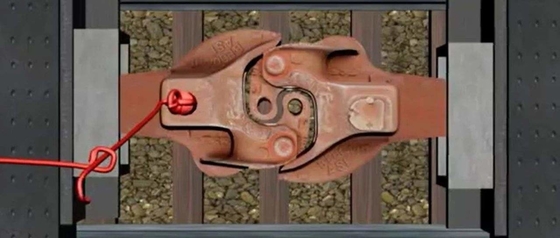
Component of Railway Coupler coupling for locomotive Rail Wagon Train Parts Railway Flexible Hinge Joint Coupler Coupling System
The coupler is composed of three parts: the hook head, the hook body and the hook tail. The thick part of the front end of the coupler is called the hook head. The rear of the coupler is called the hook tail, and there is a vertical flat lock hole on the hook tail to connect with the hook tail frame. In order to achieve hooking or unhooking, connecting or separating the vehicle, the coupler has the following three positions, that is, the three-state of the coupler: the locked position—the position where the hook of the coupler is blocked by the coupler locking iron and cannot be turned outward. The coupler is in this position when two vehicles are linked together. Unlocking position - that is, the position where the hook lock iron is lifted and the hook tongue can be turned outward as long as it is pulled. When removing the hook, as long as one of the couplers is in the unlocked position, the two linked cars can be separated. Fully open position—that is, the position where the knuckle has been fully turned outward. When two vehicles need to be linked together, as long as one of the couplers is in the fully open position, it can be linked after colliding with the other coupler. The structure of the rotary coupler is different from that of the ordinary coupler, the hook tail has a lock hole, and the hook tail pin is connected with the rotating sleeve of the hook tail frame. The end face of the hook tail is a spherical surface, which is pressed against the front and follower plate with a concave spherical surface. When the hook head is acted by torsional moment, the hook body rotates together with the tail pin and the rotating sleeve. The swivel coupler is only installed on vehicles specially designed for the Daqin railway coal transport unit combined train. One end of this kind of vehicle is equipped with a rotating coupler, and the other end is equipped with a fixed coupler. The two couplers connected in each group on the whole train are matched with each other. When the vehicle loaded with coal enters the dumper position in the coal unloading area, the dumper drives the vehicle to turn over 180 degrees to dump the coal. The rotating coupler can make the vehicle work continuously without removing the hook when the vehicle is turned over and unloading, which shortens the unloading operation time. Close-contact couplers are generally used on vehicles on high-speed railways and subways. It is small in size, light in weight, and the relative movement in all directions after the two couplers are connected is very small, which can realize a real "close connection"; at the same time, it is extremely beneficial to improve the reliability of automatic docking of brake hoses and electrical connectors.
buffer
The buffer is used to relieve the longitudinal shock and vibration caused by the change of the traction force of the locomotive during the operation of the train or the collision of the vehicles during starting, braking and shunting operations. The shock absorber has the function of dissipating shock and vibration between vehicles, thereby reducing the damage to the body structure and loaded goods. The working principle of the shock absorber is to moderate the impact force by compressing the elastic element, and at the same time use friction and damping to absorb the impact energy during the deformation process of the elastic element.
Cushioning Principle Of Railway Coupler coupling for locomotive Rail Wagon Train Parts Railway Flexible Hinge Joint Coupler Coupling System
According to the structural characteristics and working principle of the buffer, the general buffer can be divided into: friction buffer, rubber buffer and hydraulic buffer. The friction buffer is composed of front and rear parts. The front part is a coil spring (for passenger cars) or a ring spring (for trucks), and the rear part is an inner and outer ring spring, which are matched with each other by conical surfaces. Board divider. The coil spring is used to moderate the impact force, and the frictional force between the two sliding slopes of the ring spring is used to absorb energy. When the buffer is compressed by force, the rings are pressed against each other. At this time, most of the impact energy is stored in the outer ring spring. . When the external force is removed, friction is generated between the ring springs again, and part of the stored energy is converted into frictional heat energy again and dissipated, thus playing the role of buffering and damping. The head of the rubber buffer is the friction part of the wedge, which consists of three wedges with the same shape and inclined angle, the indenter and the box body. The wedge is between the indenter and the box, and the whole buffer enclosed in the box. The rubber buffer is used to alleviate the impact and consume energy by means of the friction and elastic deformation of the rubber molecules. In order to increase the capacity of the buffer, a metal friction part is installed on the head. With the help of three wedges with inclination angles, relative displacement occurs with the contact slopes between the box and the indenter under pressure, and the impact energy is consumed due to friction.
Main Production Equipment List
| No. | Equipment | Type | Qty | Status | Note |
| 1 | Vertical lathe | VTC6070 | 36 | working | Finishing workshop |
| 2 | VMC | AVL-860 | 3 | working | Finishing workshop |
| 3 | VMC | VMC850B | 14 | working | Finishing workshop |
| 4 | Multi-function machine | HTC2050n | 20 | working | Finishing workshop |
| 5 | CAK | 5085di | 10 | working | Finishing workshop |
| 6 | Steyr CNC lathe | CK7520ACK50 | 8 6 | working | Finishing workshop |
| 7 | Milling and drilling machine | XZ8210C | 2 | working | Finishing workshop |
| 8 | CNC milling and drilling machine | TY-ZT5060 | 6 | working | Finishing workshop |
| 9 | OD milling machine | MB32BX500 | 2 | working | Finishing workshop |
| 10 | Air compressor | HLGD-75 | 1 | working | Finishing workshop |
| 11 | Vertical drilling machine | Z5140A | 6 | working | Finishing workshop |
| 12 | CNC suspended tapping machine | SKXFGS.PS | 5 | working | Finishing workshop |
| 13 | CNC hobbing machine | YK3180CNC3 | 6 | working | Finishing workshop |
| 14 | Marking machine | HZP-90*160D etc. | 6 | working | Finishing workshop |
| 15 | Natural gas furnace | WLS-DZ-001 etc. | 2 | working | Forging workshop |
| 16 | Air hammer | C41-2000 etc. | 15 | working | Forging workshop |
| 17 | Press | J53-2500C etc. | 18 | working | Forging workshop |
| 18 | Ring rolling machine | D51-450A etc. | 8 | working | Forging workshop |
| 19 | Electric furnace | KGPS-600KW etc. | 10 | working | Forging workshop |
| 20 | Compressor | 175A-20.5 etc. | 3 | working | Forging workshop |
| 21 | CNC sawing machine | GZ4232 | 16 | working | Raw material workshop |
| 22 | Automatic normalization furnace | HRDW-600KW | 8 | working | Heat treatment workshop |
| 23 | Suspended gas normalization furnace | WD-0138 | 2 | working | Heat treatment workshop |
| 24 | Shot blasting machine | Q3210,Q69 etc. | 4 | working | Finishing workshop |
Main Testing and Inspection Device
| No. | Device | Type | Qty | Status | Note |
| 1 | End quenching machine | DZJ-I | 1 | working | Testing |
| 2 | Electric resistance furnace | SX2-8-12 | 2 | working | Testing |
| 3 | Inverted metallurgic microscope | 4XCE | 1 | working | Inspection |
| 4 | High temperature box resistance furnace | SX2-4-13 | 1 | working | Testing |
| 5 | Automatic digital display Rockwell hard-tester | 200HRS-180 | 1 | working | Inspection |
| 6 | Electronic Brinell hardness tester | THB-3000 | 1 | working | Inspection |
| 7 | HR-150B Rockwell hardness tester | HR-150B | 1 | working | Inspection |
| 8 | Rapid multi-element analyzer | JS-DN328 | 1 | working | Inspection |
| 9 | Electric arc furnace | JSDL-8 | 1 | working | Testing |
| 10 | Rapid multi-element analyzer(C & S) | JS-DN328 | 1 | working | Inspection |
| 11 | Infrared thermometer | AR872 | 2 | working | Inspection |
| 12 | Portable chemical composition analyzer | AR872 | 2 | working | Inspection |
| 13 | Test specimen sampler | KW30-6 | 1 | working | Inspection |
![]()

